Use line hatch styles to add a hatch with parallel lines to a shape.
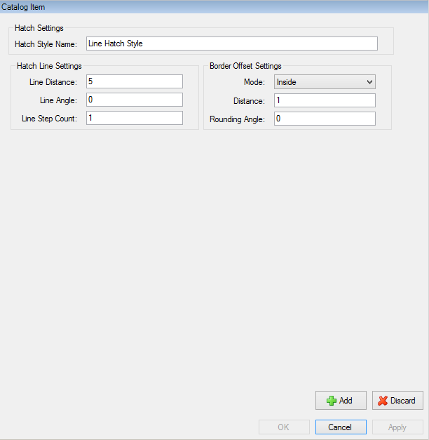
To add or edit hatch styles, use the Catalog tab of the Catalog Manager. For more information, refer to Add Hatch Styles or Edit Hatch Styles.
Table: Line Hatch Style Settings
| Hatch Style Setting | Description |
|---|---|
|
The name of the hatch style. Each hatch style in your project must have a unique name. |
|
|
The distance between each line in the hatch. |
|
|
The angle that specifies the direction of the hatch lines relative to the X axis. |
|
|
The number of times to repeat the hatch. Each time that you increase the Line Step Count value, the 180° angle between sets of hatch lines is divided by that value. For more information, refer to the example Line Step Count that follows. |
|
|
This mode specifies the type of border offset for the hatch:
|
|
|
Specifies the distance, for the margin or the overlap, between the edge of the shape and the edge of the hatch contents. |
|
|
Use this angle to keep non-rounded outside corners or to apply corner rounding to the outside corners in the border offset of the shape:
You can also specify values between 0° - 180°. For more information, refer to . |
These images show you how CADFusion repeats the hatch when you increase the Line Step Count value from 1, to 2, to 3.
Figure: Increasing the Line Step Count Value to Repeat the Hatch
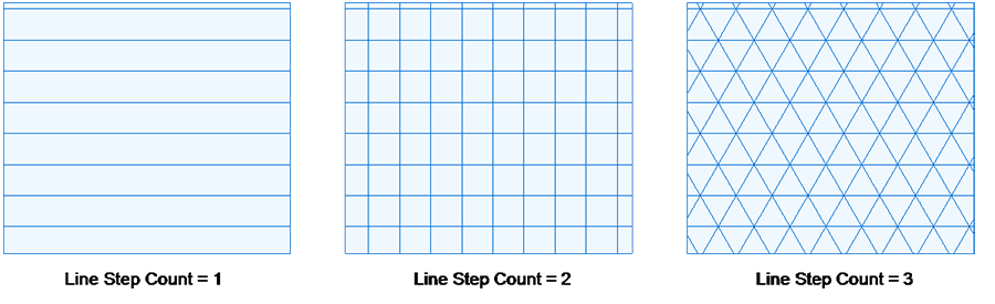
Table: Line Step Count Values
| Value | Description |
|---|---|
|
1 |
This value is the default. There is only one set of hatch lines. The angle between hatch lines is always 180°. |
|
2 |
There are two sets of hatch lines. The angle between two intersecting lines is always 90°.
|
|
3 |
There are three sets of hatch lines. The angle between two intersecting lines is always 60°.
|
.png)

